
News & Project Updates - June 2026
PCB ASSEMBLY UPDATES -
1. Important component change
The 78L09 (9vdc) regulator should be replaced with a 78L06 (6vdc) regulator to ensure reliable VCO operation. This change applies to all kits. Recent kits ship with
78L06.
2. DIP Sockets
The kit includes one DIP socket for the ATMega328 chip. To simplify fault finding and future maintenance you may wish to consider socketing all integrated circuits.
3. R25 - the electret mic resistor
R25 is only required for Electret microphones. If using a dynamic microphone this resistor should not be fitted. If you are using a dynamic mic and experience low TX deviation except when
shouting into the microphone remove R25.
4. PLL Lock, Mute and TX LEDs
Test points for "PLL lock" and "Speaker Mute" are available on the PCB. These are 5v logic-level outputs. The test points can be used to drive LEDs (assuming max 1mA/LED current). A series resistor
for each LED will be required - the value will depend on the LED colour and correspomding forward voltage drop. A third "TX" led can be driven from the "13.8vdc TX" rail.
Note that by default the PLL Lock and Audio Mute logic is "reversed". Lock LED ON = Locked (good). Mute LED on = speaker muted (quiet).
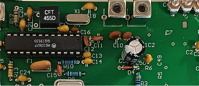
5. 455KHz filter orientation
The PCB layout supports two different 455KHz filters (one large rectangular, and a smaller square unit labelled CFT455D, both equivalent specs). Recent kits include the square CFT455D. The correct
orientation of CFT455D can be seen below:
BOARD WORK-UP & FAULT FINDING SUGGESTIONS -
6. Power the board from a 13.8vdc power supply with current limiting function (to avoid serious damage due to PCB shorts or component placement errors).
- Typical Rx current @13.8vdc (audio muted) approx. 180mA
- Typical TX current @13.8vdc approx. 600mA
7. Confirm 5vdc, 3.3vdc and 6vdc power rails are correct with DMM. If CRO available check that power rails are clean (not electrically noisy). If rail is noisy check bypass caps are correct, if bypass caps correct consider replacing voltage regulator. Noisy power rails directly impact PLL stability and audio quality. If speaker audio exhibits "regular pulsing" or low frequency (1-5Hz) noise check power rails for noise.
8. Operation of the 10.245MHz, 80MHz and 13MHz oscillators can be verified using a CRO, TinySA or nearby HF/VHF receiver tuned to relevant frequency. The PLL should maintain lock from below 1200MHz to above 1300MHz (in RX mode, measured at the PLL Lock test point).
9. Adjust P2 potentiometer so that LCD display text is readable and text contrast acceptable. Without adjustment the display backlight will typically glow (blue or another colour) but show no text.
10. If the LCD display appears totally 'dead' with no rear illumination then check the voltage at LCD panel BLK and BLA pins (BL=backlight cathode and anode). These pins should wire to edge connector BL and BL+ pins. Note the ATMega328P does not control the backlight. Dead backlight does not mean dead ATMEGA328P - it indicates power/wiring fault or faulty LCD display.
11. Pins D0, D1, D2, D3 on the LCD display panel are not used. If anything is connected to these pins there definitely is a wiring error between LCD and main PCB. Refer 2004 LCD display datasheets.
12. Non-English characters (Chinese, Cyrilic etc) appearing on the LCD panel indicate a probable wiring error between LCD and PCB. The 2004 panels are factory programmed with English character set plus a second character set (however the second character set is never activated by v4.4 firmware).
13. Confirm PLL lock via test point voltage (or Lock LED if fitted). If PLL is locked then key TX and check for RF output (via power meter or nearby 23cm receiver)
and check TX frequency (via Frequency Counter or TinySA or nearby 23cm receiver). If using a 23cm receiver do not assume your TX is exactly on frequency --> scan +/- 20KHz in case TX is
transmitting but slightly off frequency.
If you have PLL lock and13.8v TX rail is active, and no TX RF is observed at antenna then a construction error or faulty component is indicated.
_______________________________________________________________________________________________
GENERAL OBSERVATIONS
14. Frequency stability
6. Tx frequency stability is determined by the 13MHz TCXO which is multiplied approx. 100x to reach 23cm. Any noise or disturbance affecting the TCXO is also multiplied by 100x .
The original JP1BPD design has the PCB sealed into a metal "can" with feedthrough capacitors to ensure stability and minimise interference to/from the PCB. Recent constructors have however reported
no issues with plastic/3D printed cases.
If unacceptable frequency drift or PLL stability is observed (when testing the bare PCB) consider fitting the PCB into its final case (preferably metal) and ensure all wiring and coax is physically routed well clear of the RF and PLL areas of the PCB (both top & bottom sides). Then reassess PLL
stability.
15. "Genuine" MC3362 devices
7. Motorola ceased all semiconductor production around 2004.
All "Motorola" branded MC3362 devices manufactured since that date are fake.
"Genuine Motorola" MC3362 chips are no longer available through reputable suppliers such as Mouser or Digikey.
Today MC3362 devices are only available from Chinese vendors who sell "Motorola" branded MC3362 chips of unspecified quality and origin.
We have tested many MC3362 chips sourced from China, have seen one dead-on-arrival device, the rest pass minimum spec, although some are "hotter" or "more sensitive" than others.
If "no audio" from the MC3362 is observed, and all signals and voltages around the device are correct it is possible the device is faulty and requires replacement.
16. PIN diodes
The PIN diodes are small and may become "airborne" during soldering. Replacements are available cheaply from Aliexpress (you can also contact us if you are stuck). Recent kits include a few
spares diodes. Due to physical size the anode and cathode may be difficult to identify (this author cant) - consider soldering the diodes in place, then use a DMM to identify which (if any) are
back-to-front and reverse & re-solder.
17. Sequencer
The v4.4 ATMega firmware includes inbuilt TX sequencer logic to facilitate connection of an optional external relay(s) and power amplifier. All kits shipped from Australia include this firmware
(v4.4).
The logic operates as follows: When the microphone TX is pushed a positive 5v logic signal immediately appears at PCB edge connector terminal "S" (and remains at 5v until TX PTT is released).
Approximately 200msecs after PTT the PCB "TX" power rail becomes active and RF appears at the antenna connection. The signal at "S" can be used to trigger an external relay, allowing the relay to
activate & settle before RF appears, avoiding damaging "hot switching" of the TX RF.
Note1: the schematic diagram labels the sequencer output as <SEQ>.
Note2: PCB Connector pin "S" is driven directly from the ATMega328. It is a 5v logic signal (0v or 5v). Current load on this pin must be minimised (suggest >5mA, refer ATMEGA328P datasheet to be
sure). If driving a relay from this pin then driver logic will be needed to translate the voltage and current available at pin "S" to suit the relay(s).
18. Schematic Diagram
The 'source code' used to create the schematic has been lost to history, so edits are not easy.
As a result there are some minor deviations between the Australian PCB and the latest (rev 4.51) schematic.
These include:
- 78L09 regulator (and 9v supply rail) - changed to 78L06 (becomes 6v rail)
- Edge connector pin (S) on PCB conects direct to ATMEGA328P pin 16 for sequencer function (labelled "SEQ" on schematic)
- Schematic shows 13MHz TCXO powered from 3.3v zener - PCB is updated to power the TCXO from 78L33 voltage regulator.
19. RX "Birdies"
RX birdies can be heard at 1120MHz, 1200MHz, 1280MHz, 1360MHz etc. due to harmonics from the 80MHz oscillator - avoid RX on these frequencies.
20. TX Audio Improvement
The TX audio quality is heavily influenced by choice of microphone (sensitivity, noise cancelling, frequency response etc). The microphone preamp on the board is functional but basic (741
opamp).
Improved TX audio can be achieved by adding an AnalogDevices SSM2167 mic preamp between the microphone and 741 input. The SSM2167 incudes an adjustable noise gate and compressor circuitry, and is
readily available from AliExpress loose, or pre-mounted on a 15x23mm miniPCB for under $5. If using the miniPCB from Aliexpress beware that the resistors pre-fitted and labelled R1 and R2 are
incorrect to the extent that the board will not function. To use these boards totally remove R1 and R2 and replace with trimpots. Refer SSM2167 datasheet for values.
The SSM2167 is a 5vdc device and should be powered from the 5v rail. It cannot be powered from the 13.8v rail. Do not power from 3.3v rail - this rail is reserved for the PLL circuitry where noise
& stability are paramount.